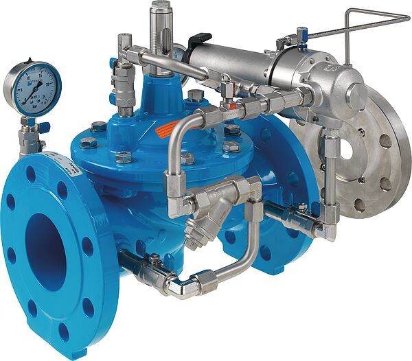
The main valve is a hydraulically operating diaphragm valve. The work energy is the inherent medium.
Most valve types operate purely hydraulically without any foreign energy.
Application
To use in drinking water systems (other media after consultation)
Limitation of an inflow into a water reservoir
Maintaining the filter flow constant whilst taking into account the water level
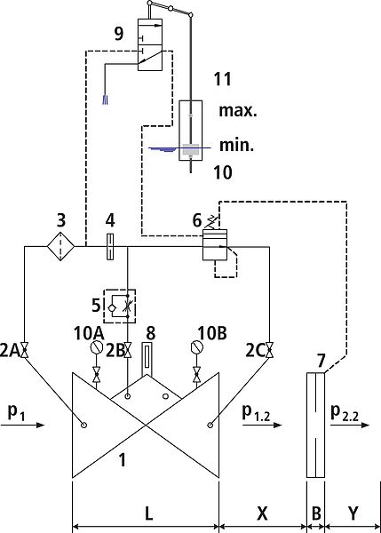
Mode of operation
The flow–control valve completely hydraulically ensures a pre–determined maximum flow, irrespective of any changes in the operating pressure taking into account the level of water in the reservoir (the float control opens when the water level is low). The nominal flow rate can be progressively varied up to ±15% via the control valve. The valve closes when the level of water in the reservoir has been reached.
Product information
To calculate the dimensions of the valve please refer to the following information:
Maximum and minimum inlet pressure (static and dynamic pressure ratios)
Counterpressure from the water level in the reservoir
Required flow rate
Permissible loss of pressure incl. measuring orifice (usually 0.5 bar over the valve and orifice plate)
Available line diameters and lengths
Construction of the valve (straight or angle design)
For the calculation basis, information on the loss of pressure and the characteristic values of the valve, please refer to the end of Chapter E.
Design
Design according to DIN EN 1074
Construction length acc. to DIN EN 558
Flange mass according to DIN 1092-2, to PN 25 DN 300
Pressure levels: PN 10 or PN 16 to DN 300, PN 25 to DN 200, higher pressures on request.
Nominal widths DN 50, DN 80, DN 100 and DN 150 available in angular design
Nominal widths 1 ½" and 2" with threaded connection (female thread)
Medium temperature up to 40°C
Installation and assembly
Shut–off valves should be fitted on both sides of the valve and a dirt trap should be installed on the inlet side of the valve. Depending on the installation situation, a mounting/dismounting adapter and an aeration and ventilation system should be provided.
The orifice plate must be installed after the valve. It is recommended that the following measurements are taken into consideration:
X = 5 x DN, distance between the valve and the orifice plate in a straight line
Y = 3 x DN, distance after the orifice plate and the shut–off component, in a straight line