


| Product attributes | |
|---|---|
| DN | 100 |
| PN | 16 bar |
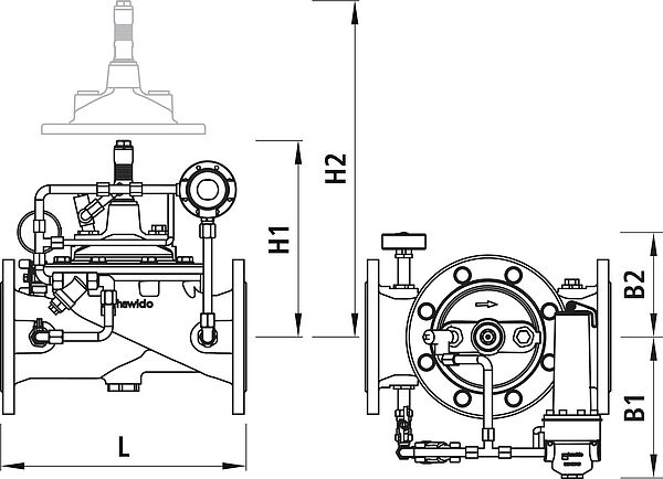
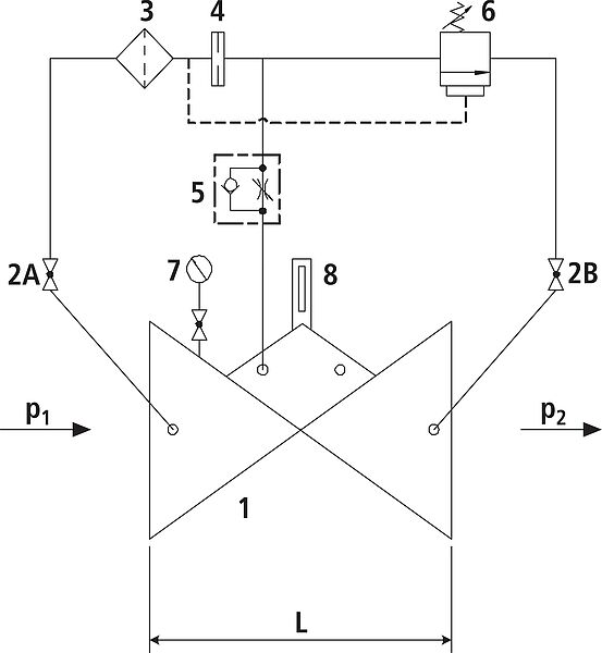
| L | 350 mm |
| B1 | 220 mm |
| B2 | 200 mm |
| H1 | 280 mm |
| H2 | 400 mm |
|
KVS l/min. |
2150 |
| weight | 35.800 kg |
|
NPK No. 411 |
833219 |
| Availability | ex warehouse |