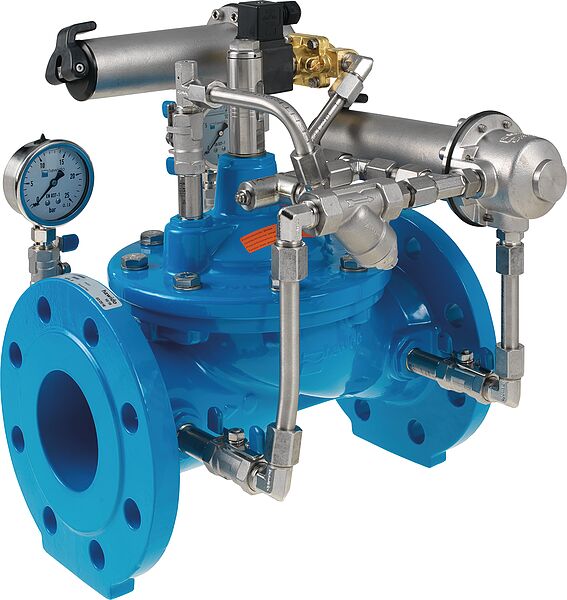
The main valve is a hydraulically operating diaphragm valve. The work energy is the inherent medium.
Most valve types operate purely hydraulically without any foreign energy.
Application
To use in drinking water systems (other media after consultation)
Increase in pressure in the network in the event of a fire (actuation via the fire department station)
Setting of the day and night operation of the network pressures (daytime operation for higher pressure, night time operation for lower network pressure)
Mode of operation
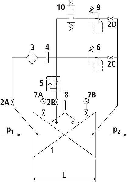
The pressure reducing valve, type 1593, works in 2 operating stages:
Operating stage a: In a normal operation, a variable inlet pressure (p1) is reduced to a constant outlet pressure (p2) by means of a control valve. Example: p1 = 12 bar / p2 = 8 bar.
Operating stage b: This second stage can be put into operation by means of the solenoid valve and the second control valve. For example: p1 = 12 bar / p2 = 10 bar.
Fluctuating flow rate and inlet pressure (p1) have no effect on the controlled outlet pressure (p2). The outlet pressure is adjustable in the range from 1.5 to 12 bar (standard design).
Product information
To calculate the dimensions of the valve please refer to the following information:
Maximum and minimum inlet pressure (static and dynamic pressure ratios)
Required outlet pressure
Voltage information for the solenoid valve
Maximum and minimum flow rates
Possible requirement for extinguishing water
Available line diameters and lengths
Construction of the valve (straight or angle design)
For the calculation basis, information on the loss of pressure and the characteristic values of the valve, please refer to the end of Chapter E.
Design
Design according to DIN EN 1074
Construction length acc. to DIN EN 558
Flange mass according to DIN 1092-2, to PN 25 DN 300
Pressure levels: PN 10 or PN 16 to DN 300, PN 25 to DN 200, higher pressures on request.
Nominal widths DN 50, DN 80, DN 100 and DN 150 available in angular design
Nominal widths 1 ½" and 2" with threaded connection (female thread)
Medium temperature up to 40°C
Installation and assembly
Shut–off valves should be fitted on both sides of the valve and a dirt trap should be installed on the inlet side of the valve. Depending on the installation situation, a mounting/dismounting adapter and an aeration and ventilation system should be provided.