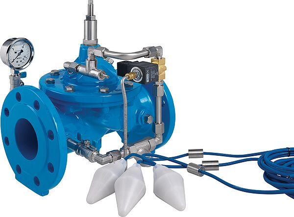
The main valve is a hydraulically operating diaphragm valve. The work energy is the inherent medium.
Most valve types operate purely hydraulically without any foreign energy.
Application
To use in drinking water systems (other media after consultation)
Level control in a reservoir or pressure–breaking shaft
Level control in an equalising basin
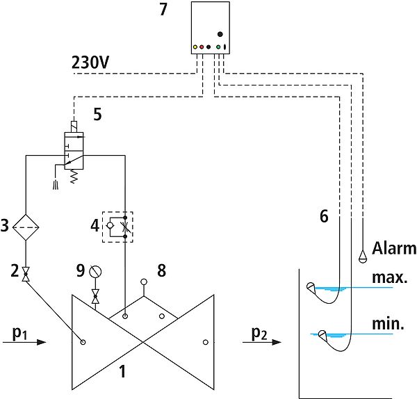
Mode of operation
The open/close valve with an electric level switch, opens or closes for the electric actuation via the level switch and the solenoid valve The valve is open when the power is off. The closing speed can be adjusted by means of a throttle non–return valve to prevent surges in pressure.
Product information
To calculate the dimensions of the valve please refer to the following information:
Maximum and minimum inlet pressure (static and dynamic pressure ratios)
Existing counterpressure of the reservoir
Required flow rate
Voltage information for the solenoid valve
Available line diameters and lengths
Construction of the valve (straight or angle design)
The level switch operates with 24 VDC. The supply voltage for the control is 230 VAC.
For the calculation basis, information on the loss of pressure and the characteristic values of the valve, please refer to the end of Chapter E.
Design
Design according to DIN EN 1074
Construction length acc. to DIN EN 558
Flange mass according to DIN 1092-2, to PN 25 DN 300
Pressure levels: PN 10 or PN 16 to DN 300, PN 25 to DN 200, higher pressures on request.
Nominal widths DN 50, DN 80, DN 100 and DN 150 available in angular design
Nominal widths 1 ½" and 2" with threaded connection (female thread)
Medium temperature up to 40°C
Installation and assembly
Shut–off valves should be fitted on both sides of the valve and a dirt trap should be installed on the inlet side of the valve. Depending on the installation situation, a mounting/dismounting adapter should be provided. If there is a free run into the water tank downstream from the valve, the slider on the outlet side can be omitted. Depending on the pressure ratios, an orifice plate should be installed on the outlet side of the valve and an opening limiter on the valve. The installation of a float protection pipe is recommended to guide the float.